Our work
You do not judge an installation by a brochure, you judge it by the connections. So here is a complete job dossier, and photographs of our own work, up close.
- 01
Survey & measuring up
2 March 2026 · Crew 2Cable route and entry recorded, connection capacity and short-circuit power requested from the grid operator, and the existing cable basement measured.
Connection capacity and short-circuit power confirmed in writing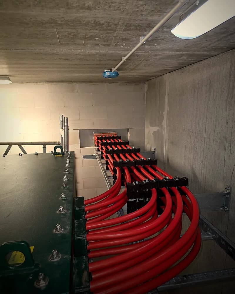
- 02
Design & busbar calculation
6 March 2026 · Crew 1Busbar sizing, short-circuit withstand and discrimination calculated; sections numbered in advance so the board is right on paper first.
NEN 1010 part 4 — overcurrent protection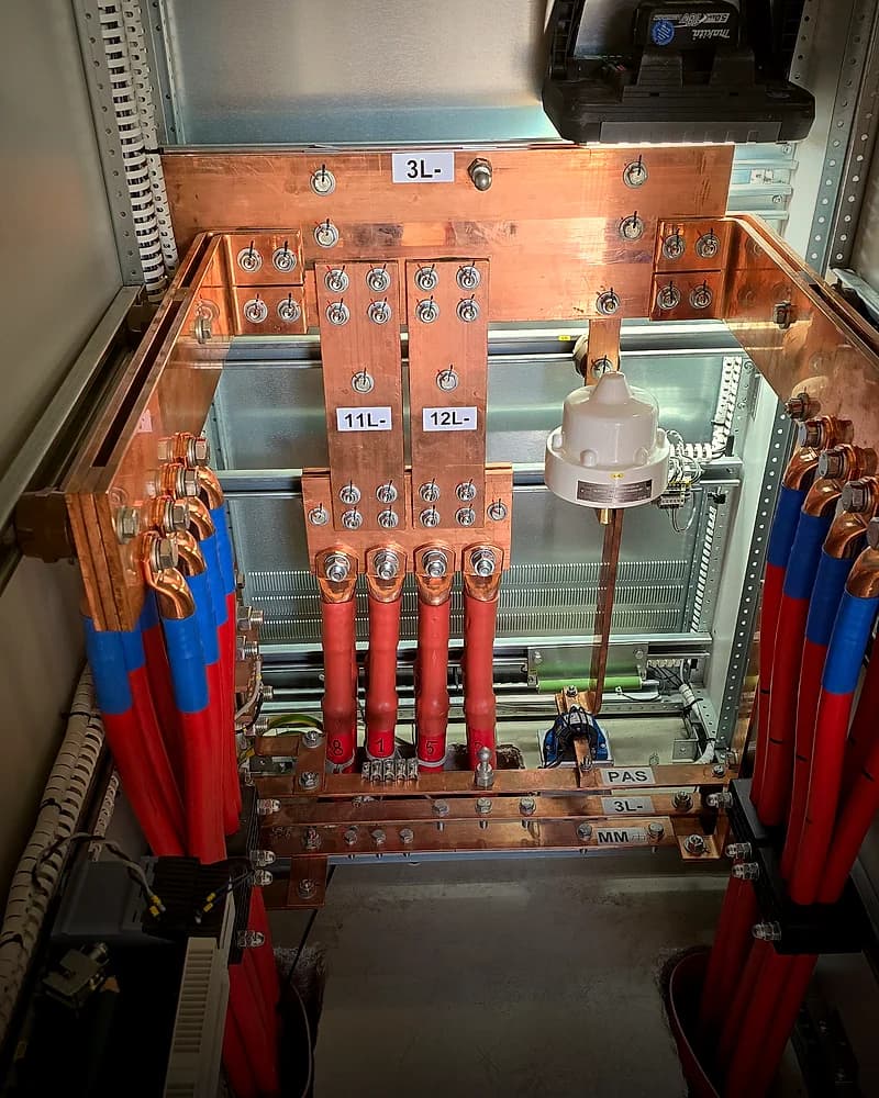
- 03
Installation
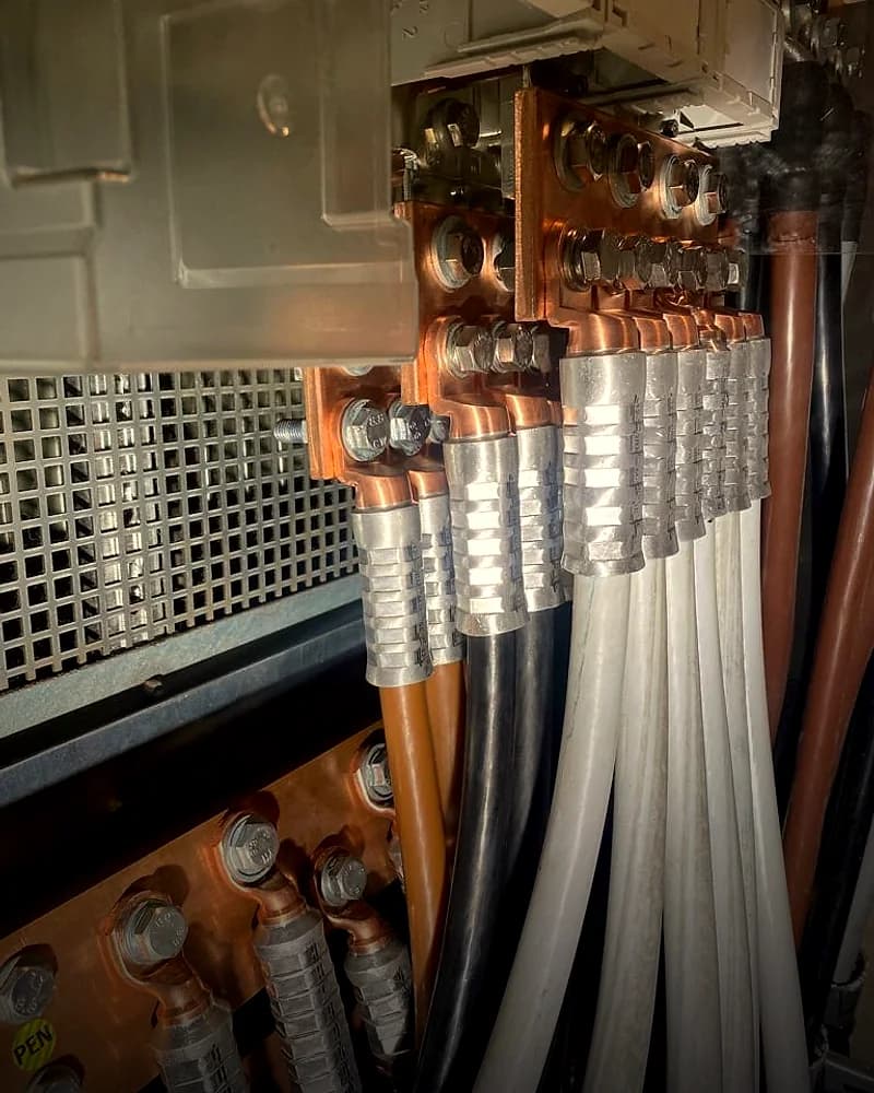
18 March 2026 · Crew 2Busbar system built up, lugs crimped with the correct die, bolts torqued to spec and marked on the spot.
Torque values logged and visibly marked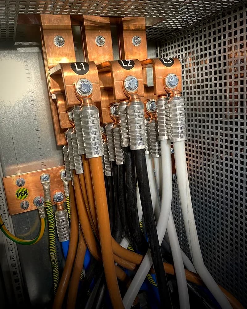
- 04
Inspection & commissioning
19 March 2026 · Crew 2Insulation resistance, earth electrode resistance and trip times measured; phases checked and labelled before anything went live.
NEN 1010 — test report issued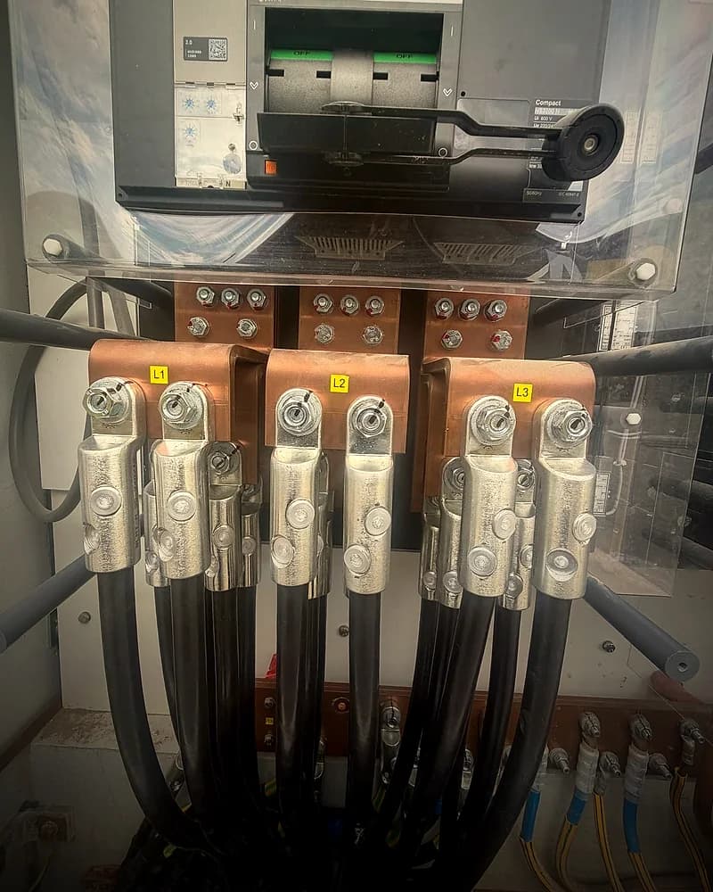
- 05
Handover & dossier
20 March 2026 · Crew 1Diagram, test report, photographs of every phase, warranty certificates and operating instructions handed over and walked through on site.
Dossier signed by client and engineer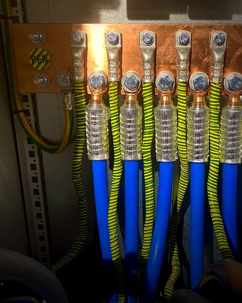
Dossier for a 3200 A main distribution board with a busbar system. Client and location are left out; the rest is exactly what the customer receives.
The work up close
Careful work survives a close-up.
Photographs of our own work, each captioned with what you are actually looking at. Note the torque marks on the bolts, the labelled phases and the matching bend radius of the cables — that is where care becomes visible.
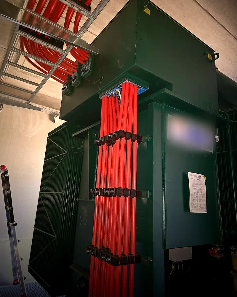
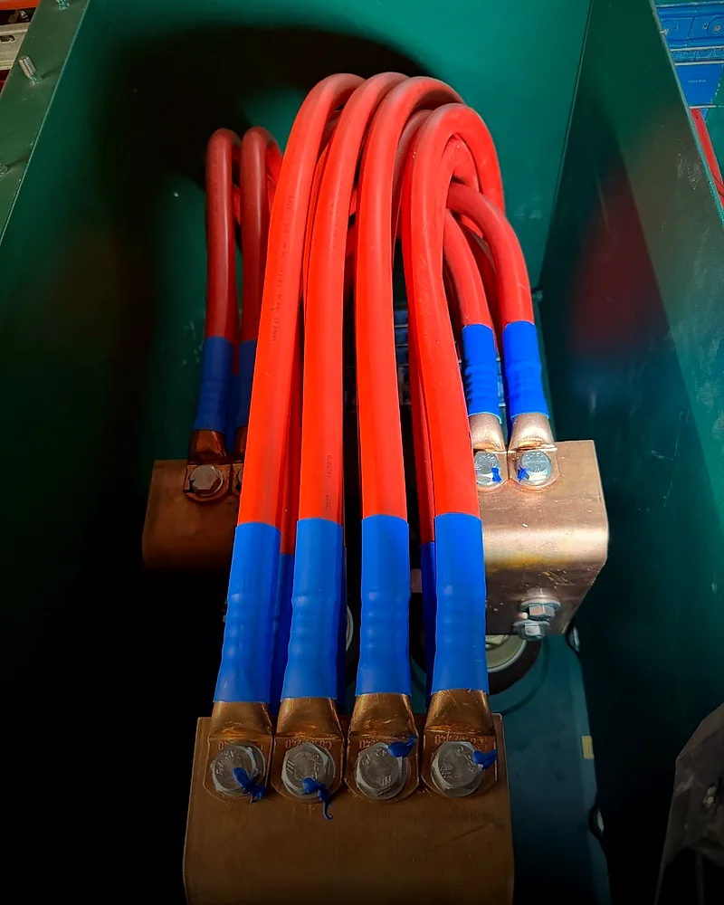
Every photograph is from our own projects. Clients and locations are left out.
Tell us what you need. A substantiated quote lands within two working days.
Four steps: what, where, when, and how we may reach you. No obligations, no sales pitch — just a calculation you can put in front of someone else.